

05 Oct 2026
Liquid-Cooling Manifolds Are Scaling from Racks to Entire Walls


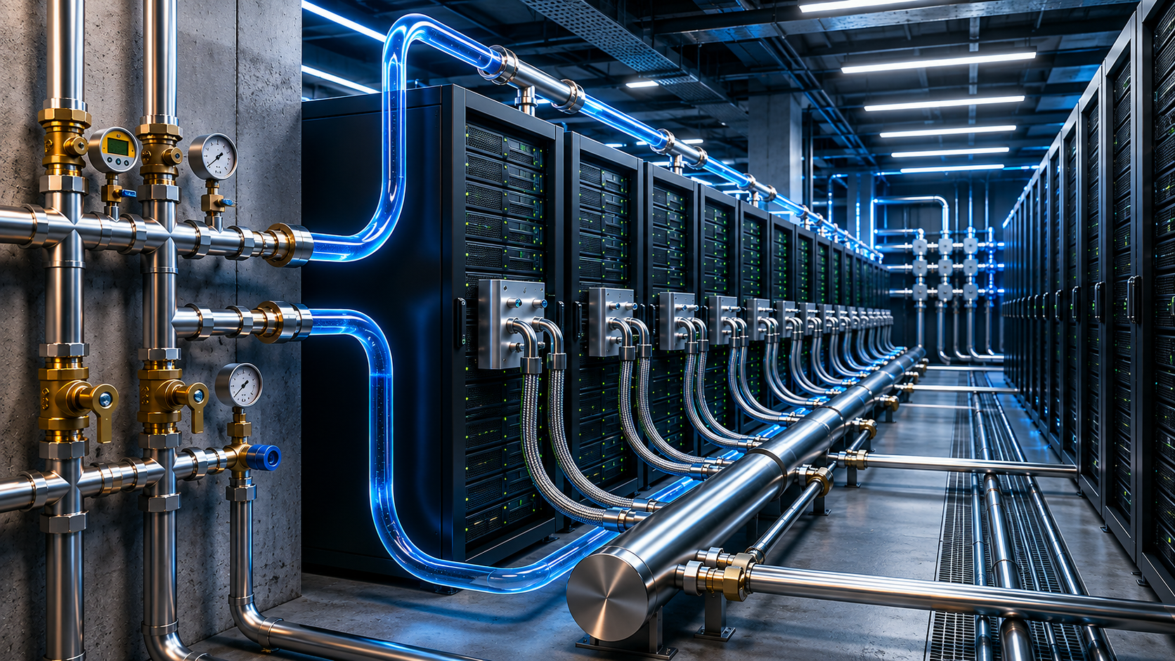
The Project Deschutes specification published by the Open Compute Project (OCP) reveals an interesting development in liquid cooling: a manifoldNote 1 is no longer necessarily just a compact component with multiple ports inside a server rack. The Wall ManifoldNote 6 described in the specification can be assembled on-site from piping sections approximately 3 meters long, with an overall length exceeding 30 meters and piping IDs of 4 inches or larger. This gives us a very intuitive way to understand how coolant distribution can expand with system scale—from the area surrounding the chips all the way to the entire data hall.
Source: Open Compute Project-Project Deschutes
What Exactly Does a Manifold Do?
Putting the complex terminology aside, the basic function of a manifold is actually quite simple: distribute coolant outward, and collect it again on the return side.
Inside a liquid-cooled server, coolant flows through Cold PlatesNote 2 mounted directly on high-heat components such as CPUs and GPUs. After absorbing heat, the coolant returns to the cooling loop. As the number of servers and cold plates increases, a single piping path is no longer sufficient, making multi-level distribution and collection designs necessary.
A liquid-cooling system commonly combines components such as a CDUNote 3, manifolds, hoses, and Cold Plates. Together, they help deliver coolant at the required temperature and flow rate reliably to the locations where heat needs to be removed.
From a Single Server to an Entire Rack Row
If we think of a liquid-cooling system as a road network, the role of manifolds becomes easier to understand by looking at the different system levels.
Cold Plate → Server
This is the level closest to the heat source. Although the internal flow passages are relatively small, factors such as how coolant flows through the cold plate, whether the required flow rate can be maintained, and how much pressure dropNote 7 is generated can directly affect cooling performance.
Rack ManifoldNote 4→ Rack
When a rack contains multiple liquid-cooled servers, a Rack Manifold is used to distribute coolant to individual IT equipment and then collect the heated coolant for return.
Row ManifoldNote 5→ Row
At the next system level, the Row Manifold connects to the liquid-cooling loop supplied by the CDU and further distributes coolant across an entire row of server racks.
At this level, design considerations extend well beyond simply determining the number of outlets. Engineers must also consider higher total flow rates, larger pipe diameters, pressure drop, system cleanliness, and on-site piping installation. OCP has also published related guidelines covering cleaning, flushing, and hydrostatic pressure testing for Row Manifolds used in liquid-cooled data centers.
Note: The Cold Plate → Rack → Row → Wall Manifold sequence shown here is a simplified system-level concept used in this article to help readers understand how liquid-cooling distribution expands across a data center. It is not an official four-level product classification defined by OCP.
Scaling Up: When a Manifold Becomes an Entire Wall
With the Wall Manifold described in Project Deschutes, the system scale extends far beyond what we might normally imagine when thinking of a conventional manifold.
The Wall Manifold described in the public specification includes a Supply Manifold and a Return Manifold for coolant supply and return, respectively. It also incorporates supporting structures such as a Drip TrayNote 8 and Mounting BlocksNote 9 to help manage potential coolant leakage and provide structural support for large piping.
The piping can be assembled from sections approximately 3 meters long and connected on-site to create a system extending more than 30 meters. Publicly specified design conditions also include a maximum coolant temperature of 55°C, a maximum working pressure of 130 psi, and differential-pressure requirements between the supply and return sides.
At this scale, engineering considerations naturally extend far beyond port diameter and fitting selection.
How should the piping be supported?
How can connection reliability be maintained?
How should thermal expansion caused by temperature changes be managed?
If leakage occurs, where should the coolant be directed?
How should future inspection and maintenance be carried out?
All of these factors become part of the overall system design.
The reliability requirements in Project Deschutes also include a Pressure Hold TestNote 10, Pressure Cycle TestNote 11, and Burst TestNote 12, which are used respectively to evaluate system sealing integrity, long-term pressure durability, and ultimate pressure capability.
Different System Scales, the Same Basic Distribution Logic
Interestingly, from compact manifolds installed inside equipment to Wall Manifolds extending more than 30 meters, the physical size may differ dramatically, but many of the fundamental questions that need to be answered during the initial design stage remain very similar:
What coolant will be used?
What is the total flow rate?
How many branches are required?
How large should the main flow passage be?
How should the ports and connections be arranged?
What is the normal operating pressure?
What test pressure must the system withstand?
Could differences in branch flow resistance cause uneven coolant distribution?
These questions also align closely with the areas Alpha Brass Controls considers when working with liquid-cooling manifold applications. Material selection, main flow-passage dimensions, number of branches, port configuration, operating pressure, pressure-test requirements, and fluid distribution are all fundamental parameters that need to be evaluated when designing a manifold.
This gives us another way to think about a manifold:
A manifold is not simply “a pipe with many holes.” It is a critical node in a liquid-cooling system that delivers coolant to the right place.
As AI computing density continues to increase, liquid-cooling systems are expanding from chips, servers, and racks to rows and even the entire data hall.
The level of manifold customization and the scale of the systems they serve can continue to grow, but the core engineering challenge remains similar: how to deliver coolant safely, reliably, and efficiently to exactly where it is needed.
Technical Term Notes
1. Manifold | Distribution / Collection Manifold
A fluid distribution or collection component that can divide one main flow path into multiple branches or combine multiple return branches into a single flow path.
2. Cold Plate
A liquid-cooling component mounted directly on high-heat devices such as CPUs and GPUs. Coolant flows through internal channels to remove heat generated by the components.
3. CDU (Coolant Distribution Unit)
A unit typically located between the data center cooling infrastructure and liquid-cooled IT equipment. It manages functions such as heat exchange, coolant circulation, flow rate, pressure, and temperature.
4. Rack Manifold | Rack-Level Manifold
A liquid-cooling supply and return manifold located at the rack level. It distributes coolant to multiple IT devices within the same rack and collects the returning coolant.
5. Row Manifold | Row-Level Manifold
A liquid-cooling supply and return manifold serving an entire row of server racks. It typically connects the CDU to multiple Rack Manifolds, distributes coolant to the racks, and collects heated coolant for return to the CDU.
6. Wall Manifold (WMF)
A large-scale coolant supply and return manifold described in Project Deschutes. It can be assembled on-site from multiple piping sections and installed along the data center infrastructure.
7. Pressure Drop
The reduction in fluid pressure caused by friction and localized resistance as fluid flows through piping, fittings, valves, or internal flow passages.
8. Drip Tray
A tray installed beneath piping or connections to collect small amounts of potential leakage and reduce the risk of coolant dripping directly onto the floor or nearby equipment.
9. Mounting Blocks
Structural components used to support and secure Wall Manifold piping so that large piping sections can be installed in their intended positions and remain mechanically stable.
10. Pressure Hold Test
A test in which the system is pressurized to a specified pressure and held for a defined period to check for leakage, pressure loss, or structural abnormalities.
11. Pressure Cycle Test
A test that repeatedly increases and decreases system pressure to simulate pressure variations during long-term operation and evaluate the durability of piping, connections, and structural components.
12. Burst Test
A test in which pressure is continuously increased to determine the ultimate pressure capability and safety margin of a component or piping system.
References
1. Open Compute Project-Project Deschutes Specification
2. Open Compute Project-Guidelines for Pre-Commission Preparation of Technology Cooling System Row Manifolds
3. Google Cloud-AI infrastructure is hot. New power distribution and liquid cooling infrastructure can help
#LiquidCooling #Manifold #DataCenterCooling #AIInfrastructure #ThermalManagement #ColdPlate #CDU #RackManifold #WallManifold #AlphaBrassControls